Quick Start
Convert your first file in five steps. This walkthrough uses a GDSII-to-DXF conversion as an example, but the same workflow applies to any format pair.
Step 1 — Select Input and Output Format
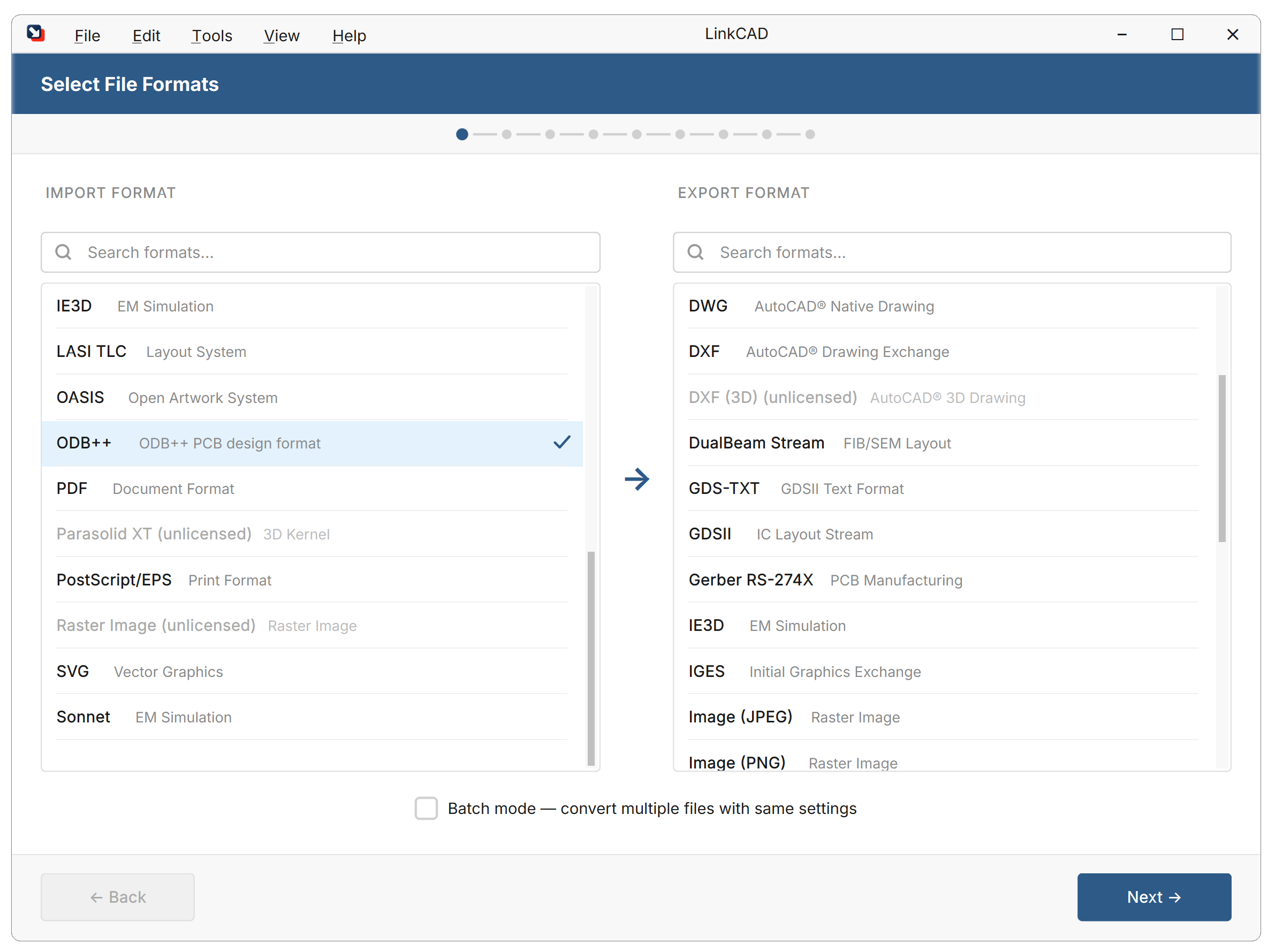
Launch LinkCAD. The conversion wizard opens automatically.
- In the Import panel, choose the input format (e.g., GDSII).
- In the Export panel, choose the output format (e.g., DXF).
Both format dropdowns are on the same screen — select them before proceeding. Click Next to continue.
Step 2 — Configure Import Options
The import options dialog shows settings specific to the chosen input format.
For most conversions, the defaults work well. Click Next to continue.
Step 3 — Configure Export Options
Set options for the chosen output format. Click Next to continue.
Step 4 — Select Input File and Convert
Select your input file (e.g., design.gds).
LinkCAD imports the file and shows the Import Log. Review any warnings, then proceed to the viewer.
Step 5 — Review, Repair, and Export
The file structure dialog shows the cell hierarchy and layer structure. Use this stage to inspect the geometry and apply optional tools from the Tools menu. Switch to the viewer to display the imported geometry.
From here you can:
- Inspect the structure using the File Structure panel
- Apply optional tools (merge polygons, repair open polylines, etc.) from the Tools menu
- Select the export destination and click Export
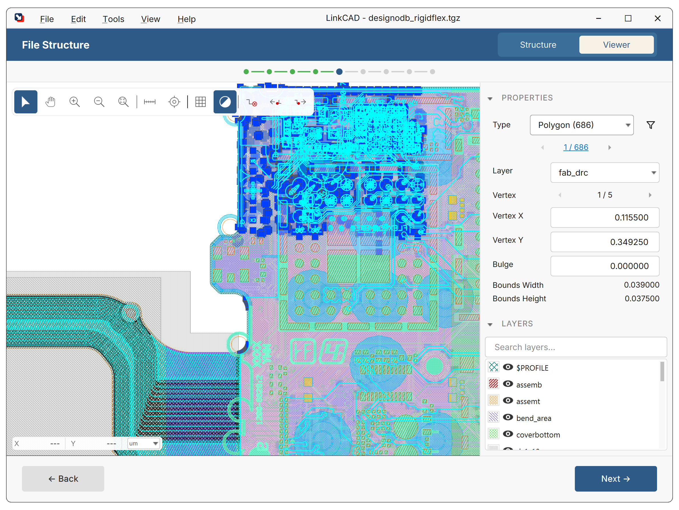
Click Next to proceed to selecting the export destination.
Step 6 — Select Export Destination and Export
Choose the output file path. After export, review the Export Log for any issues.
What’s Next
- Conversion Workflow — detailed walkthrough of every stage
- Working with Layers — map, filter, and organize layers during conversion
- Tools — apply polygon merging, boolean operations, and repair tools before export
- Batch Processing — convert multiple files at once
- Python Scripting — automate and extend LinkCAD with Python