The Conversion Workflow
LinkCAD’s main purpose is converting CAD files between formats. The conversion follows a wizard-style workflow with clear stages.
Workflow Overview
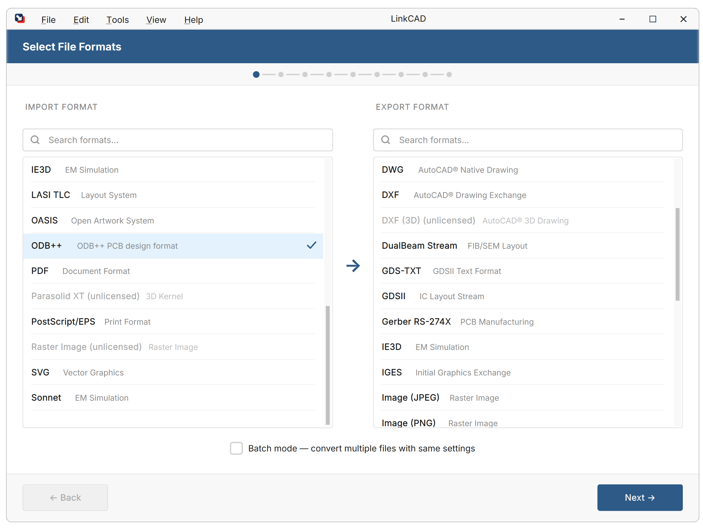
1. Select Input and Output Format
When LinkCAD opens, the conversion wizard shows both format panels side by side. Select the input format (e.g., GDSII) and output format (e.g., DXF) before proceeding.
2. Configure Input Options
Each format has specific import settings. Common options across formats:
| Option | Description |
|---|---|
| Units | Physical units of coordinates in the source file |
| Precision | Resolution of coordinate values |
| Scaling | Scale factor to apply during import |
Format-specific options are documented in each format’s reference page.
3. Configure Export Options
Set options for the chosen output format:
| Option | Description |
|---|---|
| Output units | Physical units for the exported file |
| Precision | Coordinate resolution in the output |
| Format version | Target version (e.g., DXF R12 vs. 2000) |
| Flatten | Whether to expand the cell hierarchy |
| Layer map | Map input layers to output layer names/numbers |
4. Select Input File and Import
Choose your source file:
LinkCAD reads the file and presents the Import Log. Review any warnings or errors before continuing.
5. View, Edit, and Repair
The file structure dialog shows the cell hierarchy and layer structure. Use this stage to inspect the geometry and apply optional tools from the Tools menu. Switch to the viewer to display the imported geometry.
Use this stage to:
- Inspect the cell hierarchy and layer structure
- Apply geometry tools from the Tools menu:
- Merge Overlapping Polygons — combine touching/overlapping shapes
- Flatten Hierarchy — expand cell references into a single level
- Convert Quasi-Circles — detect and reconstruct circular approximations
- Sanitize Polygons — fix self-intersecting shapes
See the Tools Reference for details on each tool.
Layer Mapping
During conversion, layers from the source format must map to layers in the target format. This can happen:
- Automatically — LinkCAD preserves layer names/numbers where possible
- Via Layer Map — a CSV file defining the mapping rules
See Layer Maps for details.
6. Select Export Destination and Export
Choose the output file path and click Export. Review the Export Log for any issues.
The conversion is complete when the export log shows no errors.
Batch Mode
To convert multiple files at once, enable Batch Mode at the initial screen. In batch mode, LinkCAD processes all files in a directory using the same import/export settings.
See Batch Processing for the full workflow.